480 Volt 12 Lead Motor Wiring Diagram : 480 Volt Motor Wiring Diagram - Wiring Diagram Networks
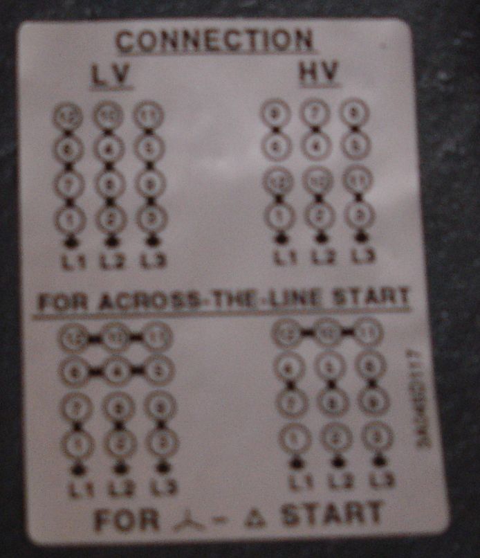
480 Volt 12 Lead Motor Wiring Diagram : 480 Volt Motor Wiring Diagram - Wiring Diagram Networks. This motor is a 6 lead dual voltage motor. Typical wiring diagrams always use wiring diagram supplied on motor nameplate connection diagrams (#co leads part winding) weg three phase motors volts / 12 lead / part winding 12 10 11 12 3 l1 l2 12 10 11 64 5 78 9. Electrical motors 12 lead, dual voltage, wye start/delta run, both voltages or 6 lead, single voltage, wye start/delta run motors designed by us motors for wye start, delta run may also be used for across the line starting using only the delta connection. 3 phase motor wiring diagram 9 leads perfect luxury 9 lead motor. It is intended to assist all of the average user in developing a proper system.
230v / 460v motor configured for 230v ( ) • brake voltage is 230v 1 motor terminal board 4 sr current relay 2 supply leads 5 terminal strip Hold the bare ends of the conductors together and twist on a wire nut. Three phase motors the wiring connection and propelling direction. L1 to t1, l2 to t2, l3 to t3, t4 to t7, t5 to t8 and t6. For example use a red wire nut to connect two 12 gauge wires.
480 Volt Motor Wiring Diagram - Wiring Diagram Networks from i0.wp.com Brake voltage matches the low motor voltage. Brake = 230v brake control: Wiring diagram arrives with several easy to stick to wiring diagram instructions. 480 volt 3 phase 6 lead wiring diagram disclaimer. I have a 277480 volt panel. Each part ought to be placed and connected with other parts in particular way. On the motor there is a low voltage wiring and a high voltage wiring. The six leads are numbered 1,2,3,6,7,8 or it's 1,2,3,7,8,9.
Otherwise, the arrangement will not work as it ought to be.
This is the standard nema connection for 12 lead delta for normal across the line starting. Brake = 230v brake control: These directions will probably be easy to understand and implement. I have to hook up a 50hp 480v motor, the schematic is gone. The six leads are numbered 1,2,3,6,7,8 or it's 1,2,3,7,8,9. Check all three wires singly t1, t2, t3 (three phases) to the ground wire. For example use a red wire nut to connect two 12 gauge wires. 3 phase motor winding resistance values, using ohm meter: Each component should be set and connected with different parts in particular way. A three phase motor is more efficient than a single phase motor because of the peculiarities of alternating current ac. Disconnect all power from the system. Delta connection, single voltage, with qty 4 current transformers, la & sc. 3 306 (03/2013) drum motor with sprockets (stm) assembly procedure 1.
I need wiring diagrams for 3 phase, 240/480v, 12 lead, 75 hp a/c industrial motors! Delta run for low voltage and wye run for high voltage. 5069f7e wiring diagram for 480 volt plug wiring resources. Brake voltage matches the low motor voltage. Hi voltage series connection for 12 lead delta is 4&7 tied,5&8 tied,6&9 tied.
Delta vs Wye - Electrician Talk - Professional Electrical ... from www.electriciantalk.com It is intended to assist all of the average user in developing a proper system. It is intended to assist all of the average user in developing a proper system. On the motor there is a low voltage wiring and a high voltage wiring. Each part ought to be placed and connected with other parts in particular way. Disconnect all power from the system. 5069f7e wiring diagram for 480 volt plug wiring resources. A three phase motor is more efficient than a single phase motor because of the peculiarities of alternating current ac. Check all three wires singly t1, t2, t3 (three phases) to the ground wire.
I can make out on the tag that the motor is dual voltage.
I have to hook up a 50hp 480v motor, the schematic is gone. It was previously fed with 480, when it was move instead of leaving the split bolts and cutting the feeders they cut the leads instead. 5069f7e wiring diagram for 480 volt plug wiring resources. Hold the bare ends of the conductors together and twist on a wire nut. Low voltage parralel connection is lines 1&6&7&12,2&4&8&10,3&5&9&11. If it's zero or reads some continuity at all, then a problem is present with the motor or cable. Brake voltage matches the low motor voltage. 480 volt motor wiring diagram. Disconnect all power from the system. Typical wiring diagrams always use wiring diagram supplied on motor nameplate connection diagrams (#co leads part winding) weg three phase motors volts / 12 lead / part winding 12 10 11 12 3 l1 l2 12 10 11 64 5 78 9. Three phase motors the wiring connection and propelling direction. Electrical motors 12 lead, dual voltage, wye start/delta run, both voltages or 6 lead, single voltage, wye start/delta run motors designed by us motors for wye start, delta run may also be used for across the line starting using only the delta connection. A wiring diagram is a streamlined conventional photographic representation of an electric circuit.
230v / 460v motor configured for 230v ( ) • brake voltage is 230v 1 motor terminal board 4 sr current relay 2 supply leads 5 terminal strip Hold the bare ends of the conductors together and twist on a wire nut. Single phase, dual voltage, 6 lead cw rotation. Wye connection, dual voltage, pws on both voltages. 3 phase motor wiring diagram 12 leads sample.
wireing for rpc from www.practicalmachinist.com I can make out on the tag that the motor is dual voltage. I need wiring diagrams for 3 phase 240480v 12 lead 75 hp ac industrial motors. Delta run for low voltage and wye run for high voltage. A three phase motor is more efficient than a single phase motor because of the peculiarities of alternating current ac. I'm sure that the motor is listed and tested for those voltages, but a 2 to 1 voltage change is not possible with a 6 lead 3 phase motor. 3 phase motor winding resistance values, using ohm meter: 277 vac wiring diagram wiring schematic diagram. The six leads are numbered 1,2,3,6,7,8 or it's 1,2,3,7,8,9.
480 volt 3 phase 6 lead wiring diagram disclaimer.
A twist lock plug wiring wiring diagram. 5069f7e wiring diagram for 480 volt plug wiring resources. Motor straight v, but has a winding schematron.orgtypical wiring diagrams always use wiring diagram supplied on motor nameplate connection diagrams (#co leads part winding) weg three phase motors volts / 12 lead / part winding 12 10 11 12 3 l1 l2 12 10 11 64 5 78 9 12 l1 l2 12 10 11 64 5 l1 l2. I need wiring diagrams for 3 phase 240480v 12 lead 75 hp ac industrial motors. 440 spark plug wiring diagram wiring diagram g11. A wiring diagram is a streamlined conventional photographic representation of an electric circuit. 12 leads terminal wiring guide for dual voltage delta connected ac induction motor. 230v / 460v motor configured for 230v ( ) • brake voltage is 230v 1 motor terminal board 4 sr current relay 2 supply leads 5 terminal strip 3 phase motor wiring diagram 12 leads. Hold the bare ends of the conductors together and twist on a wire nut. These directions will probably be easy to understand and implement. If it's zero or reads some continuity at all, then a problem is present with the motor or cable. It is intended to assist all of the average user in developing a proper system.
Each component should be set and connected with different parts in particular way 480 volt motor wiring. I'm sure that the motor is listed and tested for those voltages, but a 2 to 1 voltage change is not possible with a 6 lead 3 phase motor.